Micromod Micro-DCI: 53SL6000 Single Loop Controller Bedienungsanleitung
Stöbern Sie online oder laden Sie Bedienungsanleitung nach Ausrüstung Micromod Micro-DCI: 53SL6000 Single Loop Controller herunter. Micromod Micro-DCI: 53SL6000 Single Loop Controller User Manual Benutzerhandbuch
- Seite / 138
- Inhaltsverzeichnis
- LESEZEICHEN
- INSTRUCTION MANUAL 1
- MicroMod Automation, Inc 2
- Table of Contents 3
- 4.0 Functional Overview 4-1 4
- 5.0 Inputs/Outputs (I/O) 5-1 4
- 9.0 Commissioning 9-1 6
- Appendix A: Glossary A-1 7
- Appendix D: Prompt List D-1 7
- List of Tables 8
- List of Figures 9
- Safety Summary 11
- READ FIRST 12
- 1.0 Introduction 13
- 1.2 Controller Model Numbers 15
- 1.3 Product Specifications 15
- Thermocouple List 18
- 2DI/2DO Option Module 18
- CPU Cycle Time 19
- Control Ranges 19
- 2.1 Inspection 20
- 2.2 Site Location 20
- 2.3 Panel Mounting 20
- 2.4 Power Connections 20
- 2.5 Signal Connections 22
- 2.5.4 Analog Output AO1 23
- Signal Wiring 24
- 2.7 2DI/2DO Module 25
- 2.9 Applying Power 26
- 2.9.1 Power-up Sequence 27
- 3.0 Display Panel 28
- 3.4 Operator Mode Overflow/ 31
- Underflow Indication 31
- 3.5 Engineer Mode 32
- Backward 33
- 3.6 Entering a Pass-Key 35
- 3.7 Offline Display Pattern 35
- 3.9 Display Alphanumerics 38
- 3.10 Engineer Mode Summary 38
- 4.0 Functional Overview 40
- 4.2 Detailed Block Diagram 41
- 5.0 Inputs/Outputs (I/O) 45
- Parameter Entries 46
- Table 5-6. RTD Types 47
- 5.4 Analog Output 1 (AO1) 48
- 5.5 Discrete Inputs 49
- 5.6 Discrete Outputs 49
- 6.1 Section Overview 51
- 6.2 Characterizer 51
- 6.2.1. 3SEG Mode 52
- 6.2.2 LSEG Mode 52
- 6.2.3 PrGM Mode 53
- 6.3 Math Function Block 54
- 6.3.1 ALG Mode 55
- 6.3.2 SuMM Mode 55
- 6.3.3 PoLY Mode 56
- 6.3.4 PoWr Mode 56
- 6.3.5 LoG Mode 56
- 6.3.6 LiM Mode 56
- 57
- 7.0 Control Scheme Block 59
- Schemes 64
- Control Scheme 65
- 7.7 Control Loop Parameters 83
- 7.8 Control Scheme Signal 86
- 8.0 Eight Control Strategies 88
- 8.2 Analog Back-Up Control 90
- 8.3 Ratio Control 92
- 8.4 Auto/Manual Selector 94
- Out 95
- 8.4.8 SchM Selection 95
- 8.5.2 AI2 - Primary PV Input 96
- 8.6.1 AI1 - Primary PV Input 98
- 8.7 Dual Indicator with 100
- Re-Transmitted PV 100
- Control 101
- 8.8.3 Speed Factor Adjusting 103
- 9.0 Commissioning 104
- 9.8 Easy-Tune 106
- Actual Curve 107
- Approximated Curve 107
- 9.8.1 Executing Easy-Tune 108
- Appendix A: Glossary 112
- B.1 Overview 118
- B.2 Parts List 118
- B.3 Removal and Replacement 119
- Procedure 120
- B.5 Defaulting the Database 123
- B.6 Analog Input/Output 123
- Calibration Values 123
- B.7 Watchdog LED 123
- C.1 Overview 124
- C.2 Configuring the System 124
- Module for Datalink 124
- C.3 Protocol 124
- C.3.1 Message Types 125
- C.3.2 Transaction Examples 125
- Reference 126
- Cross Reference 128
- Reference 129
- via Datalink 131
- Appendix D: Prompt List 132
Inhaltsverzeichnis
INSTRUCTION MANUALSingle Loop Controller53SL600053SL6000 CONTROLLERPN24991ARev. 1
Figure 7-16. Auto Digital Output Path . . . . . . . . . . . . . . . . . . . . . . . . 7-19Figure 7-17
8.7 Dual Indicator with Re-Transmitted PVThe Dual Indicator allows two process variables tobe displayed and either one to be selected as theout
8.8 Proportional Speed Floating ControlThis control output is suitable for any of the controlschemes where the final control element is usually
control element, the period should be set tomatch the end-to-end travel time of the ele-ment. To operate the digital outputs in a timeproportioning m
8.8.3 Speed Factor Adjusting1.If a slide wire is connected to AI2 instead of theremote setpoint, ensure the remote/local pushbutton is set to local f
9.1 OverviewCommissioning is an iterative process of refiningthe proportional band - Pb (Pb.2), integral or resettime - tr (tr.2), and derivative tim
process control element would be moved until tem-perature increased an additional 9° from 410° to419°. Integral action would continue at each repe-ti
nitude of the step in percent of full signal spanA. Also plot a graph of the resulting transientcurve traced by the controlled variable.3.Draw a stra
Figure 9-2. Easy-Tune ProcessFigure 9-3. Preliminary Step Response -Actual CurveFigure 9-4. Preliminary Step Response - Approximated Curve53
9.8.1 Executing Easy-TuneEasy-Tune is executed from the conF-EZ moduleparameters. A typical controller display illustratingEasy-Tune being executed
Figure 9-5. Easy-Tune Display53SL6000 Instruction Manual Section 9. Commissioning9-6
GENERAL Electric Shock Hazard During MaintenanceWARNINGSDisconnect power or take precautions to ensure that contact withenergized parts is avoided whe
Table 9-2. Easy-Tune ParametersconF → EZPrompt Description DftcMControl ModeSelect the desired control action(s) forthe process: P
9.8.3.1 out ResponseThis response indicates the controller output wasinitially at extreme maximum or minimum when thepreliminary step change was atte
AdditiveFeedForward(FF)This analog input signal isadded to the PID result toform the control scheme out-put value when auto opera-tion is active.Analo
requiring standard single loopfunctionality.cASc - for control strategiesrequiring cascade functional-ity.L.LiM - for control strategiesrequiring low
optimal PID characteristicconstants.FaceplateThe entire visable front of thecontroller casework that con-tains the push buttons andLEDs.FinalControlEl
Also, a prompt that can be in-voked on the display in engi-neer mode (e.g., cn.1); ifselected, it provides scrollingcapabilities through a seriesof pa
escent process operatinglevel.(Setpoint)ProgrammerModeAn operating mode of thecharacterizer that allows 13time intervals to be definedwith ProG-chr pa
LinearModeAn operating mode of thecharacterizer whereby valuesare entered into ProG-chr-K1through K26 parameter con-stants as 13 ordered pairs (Ainput
B.1 OverviewThis section provides a parts list and maintenanceprocedures to replace the display assembly andpower supply board, to execute the self-t
WARNING: Always remove power beforeattempting to install, disassemble, or service thecontroller. Failure to remove power may result inserious persona
READ FIRSTWARNINGINSTRUCTION MANUALSDo not install, maintain, or operate this equipment without reading, understanding andfollowing the proper MicroMo
cable to new display assembly. To maintain envi-ronmental seal, ensure the rectangular gasket isplaced on the bezel. Slide bezel tabs into case andp
Figure B-3. Confidence Test ConnectionsB.4.2 Starting the Controller Confidence Test via the Faceplate Push ButtonsThe confidence
B.4.4 Controller Confidence Test SuiteDuring confidence test execution, both vertical barsare and all annunciator LEDs except WD are lit, thered dro
B.5 Defaulting the DatabaseThe database can be restored to the factory setdefault values by entering a 098 into the ProG-cS-FiX parameter using the f
C.1 OverviewThirty-two addressable controllers (0-31) can beconnected to a datalink for information transferto/from a host, which initiates all trans
Table C-2. Datalink ProtocolSymbol DescriptionCMDCommandIt is the operation to be performed or adescription of the message that followsthe Command-I.
2.Controller sends Response message.01111110 00100011 00000010 00000000 SOH Cmd + I.A. NUM LO ADD00010000 00001000 00001100
Table C-5. Datapoint AddressesType BaseAddrAddressCalculationH 09CFHAddress = H Base + (5 X H Number) = 9CFH + (5 X H Number)Address exa
C.4.3 Database Prompt-to-Datapoint Cross ReferenceTable C-6 is provided as a parameter prompt-to-datapoint cross reference.Table C-6. Prom
Table C-6. Prompt-to-Datapoint Cross ReferenceDBase Module DBaseParameterNetworkReference cn.1 Adb C005AE L034AiX B011Aut L027b1 C0
1.1 53SL6000 Controller OverviewThe 53SL6000 controller is a functionally robustinstrument capable of performing any one of manycontrol strategies.
Table C-6. Prompt-to-Datapoint Cross ReferenceDBase Module DBaseParameterNetworkReference cn.2 Adb C037AE L058AiX B014Aut L051b1 C0
Table C-6. Prompt-to-Datapoint Cross ReferenceDBase Module DBaseParameterNetworkReference EZ [Abrt] L074APLd L073cM B016dout C075dP
[0]: Logic level zero. 0.0: The value zero. 0.05: Digital filter in seconds. 0.1: Digital filter in seconds. 0.3: Digital filter in se
cSE: Control scheme analog E input. cSF: Control scheme analog F input. cSh: Control scheme digital H input. cSJ: Control scheme digital
K11: Characterizer constant 11. K12: Characterizer constant 12. K13: Characterizer constant 13. K14: Characterizer constant 14. K15: C
\S.tc: Thermocouple type CH_S. Std: Standard setpoint mode. StEP: Programmer step. StoP: Stop. StP.E: Enable oPEr prog step access.
The Company’s policy is one of continuous product improvement and the rightis reserved to modify the information contained herein without notice, or
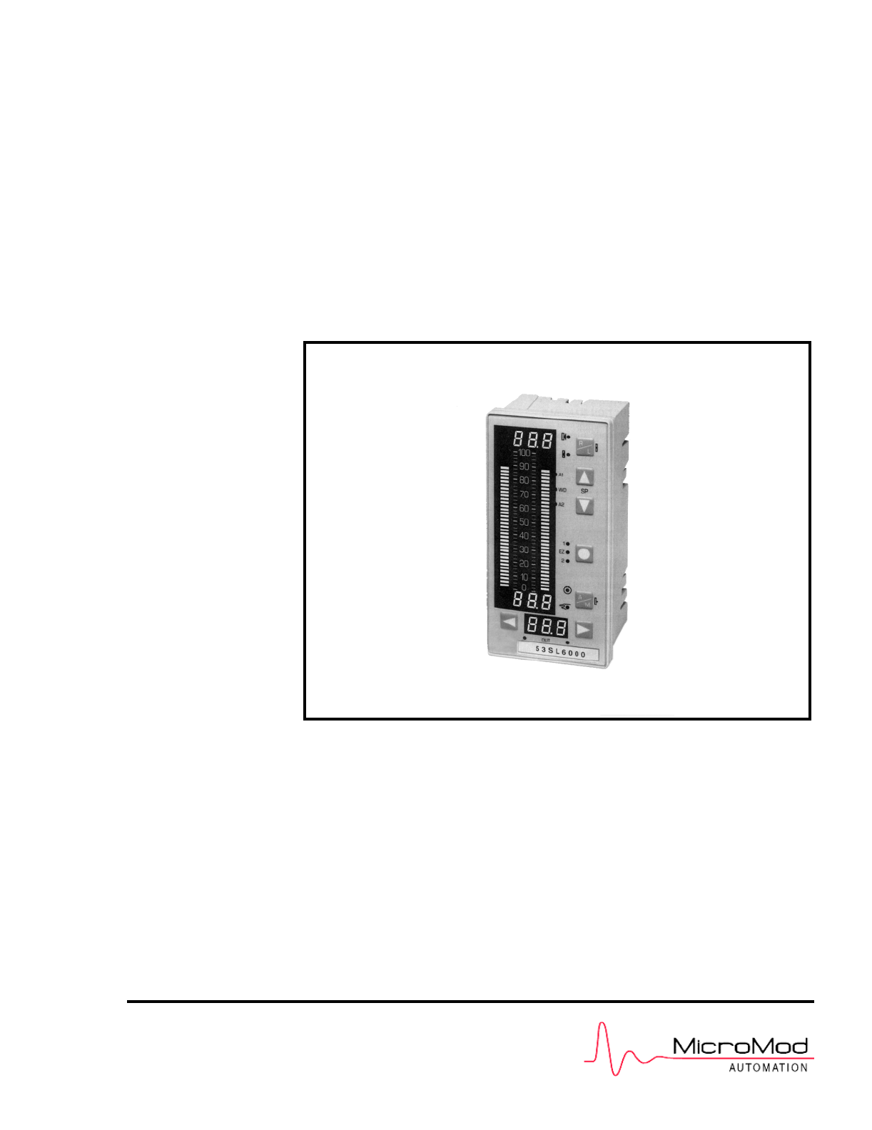
Figure 1-1. 53SL6000 Controller53SL6000 Instruction Manual Section 1. Introduction1-2
1.2 Controller Model NumbersThe 53SL6000 controller model numbers are de-scribed in Table 1-1.Table 1-1. 53SL6000 Model Numbers53 SL6♦♦♦A♦♦Controlle
Thermal Shock± 66°C/hr ( ± 150.8° F /hr)(storage/transport)Physical Shock15 g 1/2 sine, 11 ms(operation)Physical ShockASTM D4169, DC1(storage/transmit
Analog Output 1(referenced to power common)Number1Rated Signal Range0/4 to 20 mAControl Range0 to 21.5 mANo-Load Voltage≤ 24 VLoad Range0 to 750 ohmsF
(-320° to 1560° F)Copper RTDsCopper 10 Ohm RTDα = 0.00427-200° to +260° C(-320° to 500° F)Copper 53 Ohm RTDα = 0.00427-50° to +150° C(-55° to 300° F)C
cal 24 V/4 A ohmic Amp switchingoperationsSpark SuppressorIn series 5nF/51 ohm with varistor420 Veff in parallelElectrical Isolation1000 V contact coi
MicroMod Automation, Inc. The Company MicroMod Automation is dedicated to improving customer efficiency by providing the most ost-effective, applica
2.1 Inspection Inspect the equipment upon arrival for damage thatmay have occurred during shipment. If damage issuch that faulty operation is like
Figure 2-1. Panel Cutout and Installation53SL6000 Instruction Manual Section 2. Installation and Power-Up Procedures2-2
Figure 2-2. Power Plug2.4.1 24 V DC Power ConnectionsFigure 2-3. 24 V DC Power ConnectionsRefer to Figure 2-3 to make the following connec-tions:1.
Figure 2-5. Signal PlugFigure 2-6. Signal Plug ConnectionsNOTE 1: Shielded signal cable (two-wire) shouldbe used in electrically noisy locations.NOT
2.6 Universal Analog Input ModuleThis information applies to only those controllerswith an optional universal analog input module.2.6.1 Universal An
Figure 2-8. Input Configurations2.7 2DI/2DO ModuleThis information applies to only those controllerswith the optional 2DI/2DO module.2.7.1 2DI/2DO B
Signal input connections for the 2DO six terminalplug are illustrated in Figure 2-11. Both, DO1 andDO2 are Form C relays. The contact load capaci-ti
controller powers up in the last state it was in be-fore power was removed.2.9.1 Power-up SequenceThe power-up sequence is as follows:1.At power-up,
3.1 Display Panel OverviewAs shown in Figure 3-1, the controller display panelcontains three digital read-out (dro) fields, two ver-tical bar indicat
Item/LED Off On Blink-ingDescription8 - R X Remote/Ratio.X Remote requested, butnot granted (RemoteEnable [RE] not true).9 - L X Local Setpoint.X Setp
Table of ContentsSafety Summary IRead First II1.0 Introduction 1-11.1 53SL6000 Controller Overview . . . . . . . . . . . .
Table 3-1. Operator Mode Display ItemsItem Call-Out Description1 PV dro It is the process variablevalue in engineering units.2 PV bar It indicates th
Table 3-1. Operator Mode Display ItemsItem Call-Out Description20Select Modeand Loop 1/2Push ButtonPressing this pushbutton in operatormode with an a
3.5 Engineer ModeThe controller parameters and path connectionsare configured in engineer mode. Engineer modeis also used to initiate the Easy-Tune
Figure 3-5. Editing a ParameterNOTE 1: There is a 12.5 second time-out thatoccurs if a parameter prompt is not selected inengineer mode.NOTE 2: oPEr
Figure 3-6. Deselecting and ScrollingBackwardFigure 3-7. Editing a Red dro ValueFigure 3-8. Moving the Red dro DecimalPoint3.5.2.4 Editing the Tag
Figure 3-9. Editing a tAG3.6 Entering a Pass-KeyIn engineering mode, access to the ProG and conFmenus can be selectively restricted, as each menuhas
• If exiting the conF or ProG menus in engineermode, the controller goes offline and a blinkingoFF prompt appears in the red dro immediatelyafter the
Table 3-3. oPEr Menu SelectionsPrompt Description DftAdbAlarm DeadbandSpecifies the hystersis (gap)between alarm trigger and reset.This value is used
Table 3-3. oPEr Menu SelectionsPrompt Description DftEtrEasy-Tune Reset TimeResultant reset time valuecalculated by Easy-Tune. (It isenabled with c
Figure 3-13. Engineer Mode Prompt Path Summary53SL6000 Instruction Manual Section 3. Display Panel3-12
3.5 Engineer Mode . . . . . . . . . . . . . . . . . . . . . . . . . . . . . . . 3-53.5
4.1 Simplified Block DiagramAs shown in Figure 4-1 below, the internal opera-tions of the 53SL6000 Controller can be classifiedinto nine major functio
5.Discrete Input Logic Blocks - two input logicblocks permit discrete input signals to be eventgated with internal controller signals accordingto any
selections are path connections to the controlscheme block inputs A - F.The digital signal selections ([1] - /do8) areavailable to characterizer input
module; otherwise, they will not appear in theoPEr prompt list.7.Discrete output logic blocks (Logic 3 and 4) -parameter inputs to both logic modules(
Figure 4-2. Detailed Functional Controller Block DiagramSection 4. Functional Overview 53SL6000 Instruction Manual4-5
5.1 I/O OverviewThis section provides functional descriptions andapplicable parameter definitions for all of the con-troller inputs and outputs to in
5.3 Universal Analog Input ModuleThe universal analog input module can processone or two inputs, as determined by the type ofoption installed. A sin
Table 5-3. Input Type Prompts(conF Menu → Ai.3, Ai.4 Modules)Prompt Description SeeTabledtotDelta Pulse Totalizer (pulse input,incremental sum) 0-100
Table 5-7. Frequency/Pulse Input Types(conF Menu → Ai.3, Ai.4 Modules)Prompt Description DfttYPEMake prompt selection from Table5-3. Applicable type
Table 5-10. Analog Output Registers(ProG Menu → Ao Module)Prompt Description DftAo1.iAo2.iAo3.i(cont)Analog Output Connections (cont)Specifies the in
7.0 Control Scheme Block 7-17.1 Control Scheme Block . . . . . . . . . . . . . . . . . . . . . . . .
Table 5-12. Discrete Output Selections(ProG Menu → do Module)Prompt Description DftinV1 -inV8Discrete Output Invert0-on: it indicates a value of zero
6.1 Section OverviewSignal modification includes the altering, adjusting,selecting, or limiting of the analog input signal val-ues and digital input
Table 6-1. Characterizer Parameters(ProG Menu → chr Module)Prompt Description DftK01 -K26Assignments for K01 through K26 forthe three segment (3SEG)c
To ensure the piecewise approximation specifies arealizable function, the values for the coordinateinputs, which are stored in characterizer constants
•When engineer mode is exited and run is se-lected, the setpoint will move to the assignedvalue for the duration of its corresponding timeinterval.•To
Table 6-2. Math Function Block Parameters(ProG Menu → Fnc Module)Prompt Description DftFnc.MMath Function Block Mode SelectThis mode parameter is use
6.3.3 PoLY ModeThis is a third order polynomial equation which op-erates on an algebraic combination of the four ana-log inputs. The constants K1 th
6.3.7 SEL ModeThe selector allows one of four analog input valuesto be passed to the analog output based on thevalues of the two digital inputs (E an
Table 6-3. Logic Block Parameters(ProG Menu → LG Module)Prompt Description DftLG1.MLG2.MLG3.MLG4.MLogic Blocks 1 - 4 Mode SelectThese mode parameters
7.1 Control Scheme BlockThe control scheme block, which is the primaryfunctional element of the controller, provides thecapability to select and impl
8.5 Single Station Cascade Control . . . . . . . . . . . . . . . . . . . . . . . . 8-98.5.1 AI1 - S
Figure 7-1. Input Signal Designators by Control Scheme53SL6000 Instruction Manual Section 7. Control Scheme Block7-2
Table 7-1. Control Signal DescriptionsSignal DescriptionAutAuto StatusFor SnGL, cASc, L.LiM, and h.LiM controlschemes, Aut selects the PID algorithmr
Table 7-1. Control Signal DescriptionsSignal DescriptionSPtSSetpoint Track StatusFor the SnGL, cASc, L.LiM, and h.LiMcontrol schemes, SPtS selects th
Figure 7-2. Control Signal Logic PathsSection 7. Control Scheme Block 53SL6000 Instruction Manual7-5
7.4 Signal Paths for the SnGL, cASc, L.LiM, and h.LiM Control SchemesFigure 7-3 is a graphical representation of the con-trol scheme bloc
• Figure 7-15. Manual Output Path• Figure 7-16. Auto Digital Output Path7.5 Signal Paths for the in.Ld Control SchemeThe indicator/loader (i
Figure 7-3. SnGL, cASc, L.LiM, and h.LiM Signal Paths53SL6000 Instruction Manual Section 7. Control Scheme Block7-8
Figure 7-4. Common Setpoint Logic PathsFigure 7-5. Local Standard (Std) Setpoint PathSection 7. Control Scheme Block 53SL6000 Instruction Manual7-9
Figure 7-6. Remote Ratio Setpoint PathFigure 7-7. StV Setpoint Tracking53SL6000 Instruction Manual Section 7. Control Scheme Block7-10
Figure 7-8. PVt Setpoint TrackingSection 7. Control Scheme Block 53SL6000 Instruction Manual7-11
9.8.3.11 PidL Response . . . . . . . . . . . . . . . . . . . . . . . 9-89.8.3.12 cM Response . .
Figure 7-9. cASc Control Scheme Setpoint Path53SL6000 Instruction Manual Section 7. Control Scheme Block7-12
Figure 7-10. Pb, td, and tr PID PathsSection 7. Control Scheme Block 53SL6000 Instruction Manual7-13
Figure 7-11. Pb, td, tr, and FF PID Paths53SL6000 Instruction Manual Section 7. Control Scheme Block7-14
Figure 7-12. Pb, td, tr, and FF PID Paths with EXrFSection 7. Control Scheme Block 53SL6000 Instruction Manual7-15
Figure 7-13. Output Tracking Path53SL6000 Instruction Manual Section 7. Control Scheme Block7-16
Figure 7-14. Auto Output PathSection 7. Control Scheme Block 53SL6000 Instruction Manual7-17
Figure 7-15. Manual Output Path53SL6000 Instruction Manual Section 7. Control Scheme Block7-18
Figure 7-16. Auto Digital Output PathSection 7. Control Scheme Block 53SL6000 Instruction Manual7-19
Figure 7-17. in.Ld Control Scheme Alarmed Variable Input53SL6000 Instruction Manual Section 7. Control Scheme Block7-20
Figure 7-18. in.Ld Control Scheme Auto Input with Digital OutputSection 7. Control Scheme Block 53SL6000 Instruction Manual7-21
List of TablesTable 1-1. 53SL6000 Model Numbers . . . . . . . . . . . . . . . . . . . . . . . . 1-3Ta
Figure 7-19. in.Ld Control Scheme Output Tracking53SL6000 Instruction Manual Section 7. Control Scheme Block7-22
Figure 7-20. in.Ld Control Scheme Manual OperationSection 7. Control Scheme Block 53SL6000 Instruction Manual7-23
7.6 Control Scheme ParametersTable 7-2 provides the control scheme ProG-cSmodule parameters. These parameters set the ba-sic operation of the contro
Table 7-2. Control Scheme Parameters(ProG Menu → cS Module)Prompt Description DftcS.hcS.JcS.KcS.LControl scheme cS.h - cS.L DigitalInputsSpecifies pa
Table 7-3. Control Selections(conF Menu → cn.1, cn.2 Modules)Prompt Description DfttrReset Time (see Section 9.3)Specifies the time in minutesrequir
Table 7-3. Control Selections(conF Menu → cn.1, cn.2 Modules)Prompt Description DftSSrSetpoint Slew RateSpecifies in engineering units persecond the
Table 7-3. Control Selections(conF Menu → cn.1, cn.2 Modules)Prompt Description DftrSv(cn.1only)Reverse ValveSpecifies whether 100% outputshould be
Figure 7-21. Control Schemes Signal Connector Pin AssignmentsSection 7. Control Scheme Block 53SL6000 Instruction Manual7-29
This section provides information to implementeight commonly used control strategies:•Single Loop Control with Remote Setpoint.•Analog Back-up Control
8.1.1 AI1 - Process Variable InputThis analog input signal value is compared to thecontrol setpoint to determine the control outputvalue.Applicable p
List of FiguresFigure 1-1. 53SL6000 Controller . . . . . . . . . . . . . . . . . . . . . . . . . .
8.2 Analog Back-Up ControlThe direct digital control/analog back-up strategyis used in operations where a remote computer isnormally controlling the
8.2.1 AI1 - Process Variable InputThis analog input signal value is compared to thecontrol setpoint to determine the control outputvalue.Applicable p
8.3 Ratio ControlRatio control is used where one variable, called thecontrolled variable, must be automatically main-tained in definite proportion to
Applicable parameter that may require configura-tion change:Section 5.6, ProG-do-inV2.8.3.5 DI1 - Force Control Output Contact Inpu
8.4 Auto/Manual SelectorAn auto/manual selector application is illustrated inFigure 8-8. This application is implemented withthe controller default
8.4.4 D02 - PV1 Low Alarm Contact OutD02 is closed (on) when the alarmed process vari-able value, PV1, is not within the process a
8.5 Single Station Cascade ControlA single station cascade control strategy is illus-trated in Figure 8-10. This control strategy is imple-mented wit
8.5.4 DO2 - Secondary PV Low Alarm Contact OutD02 is closed (on) when the secondary processvariable value is not within the lo
8.6 Single Station Override ControlWith Single Station Override Control, two standardPID control loops function as two interdependentvariables, prima
Applicable parameter that may require configura-tion change:Section 5.6, ProG-do-inV1.8.6.4 DO2 - Primary PV Low Alarm Contact
Verwandte Produkte und Handbücher für Ausrüstung Micromod Micro-DCI: 53SL6000 Single Loop Controller
 (99 Seiten)
(123 Seiten)
(71 Seiten)
(201 Seiten)
(6 Seiten)
(20 Seiten)
(4 Seiten)
(70 Seiten)
(24 Seiten)
(42 Seiten)
(82 Seiten)
(99 Seiten)
(123 Seiten)
(71 Seiten)
(201 Seiten)
(6 Seiten)
(20 Seiten)
(4 Seiten)
(70 Seiten)
(24 Seiten)
(42 Seiten)
(82 Seiten)
© 2020, manymanuals.de. Alle Rechte vorbehalten. | 1.448 s |
 Manymanuals.com
 Manymanuals.de
 Manymanuals.fr
 Manymanuals.it
 Manymanuals.pl
 Manymanuals.cz
 Manymanuals.es
 Manymanuals-pt.com
Kommentare zu diesen Handbüchern